Splitter Electrical Specifications
Maximum Ratings
Features
∑ catv
∑ cellular
∑ wideband, 10 to 800 MHz
∑ good input VSWR, 1.35:1 typ.
∑ excellent output VSWR, 1.16:1 typ.
∑ shielded metal case
∑ solder plated J-leads for good solderability
& strain relief
Applications
Operating Temperature
-40įC to 85įC
Storage Temperature
-55įC to 100įC
Power Input (as a splitter)
0.5W max.
Internal Dissipation
0.275W max.
CASE STYLE: BL372
PRICE: $139.95 ea. (Qty.1-9)
L = 10-100 MHz M = 100-400 MHz U = 400-800 MHz
L
Typ. Min.
M
Typ. Min.
U
Typ. Min.
FREQ.
RANGE
(MHz)
PHASE
UNBALANCE
(Degrees)
L
Max.
U
Max.
M
Max.
ISOLATION
(dB)
INSERTION LOSS (dB)
ABOVE 12.0 dB
S
Typ.
OUT
Typ.
L
Typ. Max.
M
Typ. Max.
U
Typ. Max.
VSWR
(:1)
AMPLITUDE
UNBALANCE
(dB)
L
Max.
U
Max.
M
Max.
f
L
- f
U
10-800
32 20
23 15
20 15
1.6 3.5
1.9 3.5
2.2 4.0
10
15
30
0.8
1.2
2.1 1.4
1.16
Freq.
(MHz)
Insertion Loss
(dB)
S-1
Amplitude
Unbalance
(dB)
Isolation
(dB)
VSWR
S
VSWR
1
Phase
Unbalance
(deg.)
1-2
4-5
Typical Performance Data
Demo Board MCL P/N: TB-220
Suggested PCB Layout (PL-107)
JEPS16-1W-75
INSERTION LOSS
10
12
14
16
18
20
10
168
326
484
642
800
FREQUENCY (MHz)
INS
E
RT
IO
N LO
S
S
(
d
B
)
JEPS16-1W-75
ISOLATION
0
20
40
60
80
100
10
168
326
484
642
800
FREQUENCY (MHz)
IS
O
L
A
T
IO
N (
d
B
)
1-2
4-5
JEPS16-1W-75
VSWR
1.0
1.1
1.2
1.3
1.4
1.5
10
168
326
484
642
800
FREQUENCY (MHz)
VSWR
#S-VSWR
#1-VSWR
10.00
13.63
0.08
32.93
55.57
0.52
1.44
1.36
15.00
13.55
0.08
34.22
57.85
0.60
1.37
1.30
30.00
13.51
0.06
34.73
60.25
0.94
1.33
1.27
50.00
13.57
0.05
33.92
59.62
1.41
1.33
1.27
70.00
13.61
0.07
32.84
58.13
1.94
1.33
1.27
100.00
13.66
0.10
31.16
55.29
2.77
1.35
1.26
150.00
13.74
0.19
28.73
51.63
3.96
1.33
1.25
225.00
13.79
0.41
26.04
48.57
5.29
1.35
1.23
300.00
13.81
0.64
24.20
46.71
6.25
1.37
1.20
375.00
13.84
0.85
22.95
45.76
7.94
1.38
1.17
450.00
13.90
0.95
22.19
46.13
9.85
1.37
1.14
525.00
13.97
0.90
21.86
48.25
12.00
1.35
1.13
600.00
14.09
0.69
21.88
53.79
14.17
1.29
1.14
675.00
14.26
0.60
22.07
54.24
16.42
1.20
1.17
800.00
14.76
1.12
21.92
43.86
20.72
1.16
1.23
electrical schematic
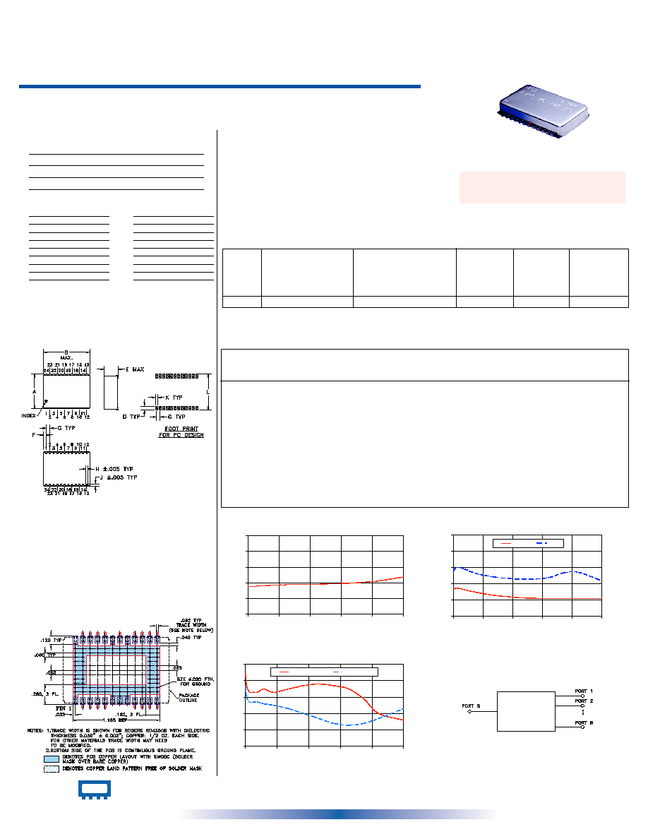
Outline Drawing
Pin Connections
A
B
C
D
E
F
.940
1.426
--
.100
.250
.163
23.88
36.22
--
2.54
6.35
4.14
G
H
J
K
L
wt
.100
.047
.065
.065
.970
grams
2.54
1.19
1.65
1.65
24.64
6.4
Outline Dimensions ( )
inch
mm
Demo Board MCL P/N: TB-220
Suggested PCB Layout (PL-107)
SUM PORT
18
PORT 1
2
PORT 2
3
PORT 3
4
PORT 4
5
PORT 5
9
PORT 6
10
PORT 7
11
PORT 8
12
PORT 9
13
PORT 10
14
PORT 11
15
PORT 12
16
PORT 13
20
PORT 14
21
PORT 15
22
PORT 16
23
GROUND
1,6,7,8,17,19,24
+ RoHS compliant in accordance
with EU Directive (2002/95/EC)
The + suffix identifies RoHS Compliance. See our web site
for RoHS Compliance methodologies and qualifications.
16 Way-0į 75
10 to 800 MHz
Power Splitter/Combiner
Surface Mount
REV. C
M102713
ED-6349/1
JEPS-16-1W-75
HY/TD/CP
060131
INTERNET http://www.minicircuits.com
P.O. Box 350166, Brooklyn, New York 11235-0003 (718) 934-4500 Fax (718) 332-4661
Distribution Centers
NORTH AMERICA 800-654-7949 ∑ 417-335-5935 ∑ Fax 417-335-5945 ∑ EUROPE 44-1252-832600 ∑ Fax 44-1252-837010
Mini-Circuits
ģ
Mini-Circuits ISO 9001 & ISO 14001 Certified
JEPS-16-1W-75+
JEPS-16-1W-75